Programmation de la carte Discovery : Différence entre versions
De Wiki L.A.B
(Programmation de la carte Discovery) |
|||
| (Une révision intermédiaire par le même utilisateur non affichée) | |||
| Ligne 3 : | Ligne 3 : | ||
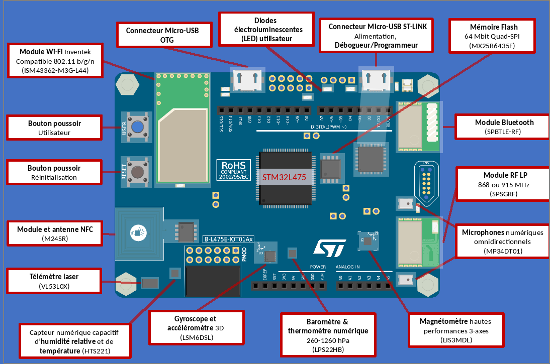
| − | [[File: | + | [[File:DiscoSchema.png|none|Présentation schématique]] |
* Ultra-low-power STM32L4 Series | * Ultra-low-power STM32L4 Series | ||
Version actuelle en date du 19 décembre 2018 à 12:47
Nous présentons ici quelques programmes d'exemples.
Sommaire
Introduction
- Ultra-low-power STM32L4 Series
- MCUs based on Arm® Cortex®-M4 core,
- 1 Mbyte of Flash memory,
- 128 Kbytes of SRAM;
- 64-Mbit Quad-SPI (Macronix) Flash memory
- Bluetooth® V4.1 module (SPBTLE-RF)
- Sub-GHz (868 MHz or 915 MHz) -programmable RF module;
- 802.11 b/g/n compliant Wi-Fi® module from Inventek Systems (ISM43362-M3G-L44)
- Dynamic NFC tag based on M24SR with its printed NFC antenna
- 2 digital omnidirectional microphones (MP34DT01)
- Capacitive digital sensor for relative humidity and temperature (HTS221)
- High-performance 3-axis magnetometer (LIS3MDL)
- 3D accelerometer and 3D gyroscope (LSM6DSL)
- 260-1260 hPa absolute digital output barometer (LPS22HB)
- Time-of-Flight and gesture-detection sensor (VL53L0X)
- 2 push-buttons (user and reset)
- USB OTG FS with Micro-AB connector
- Expansion connectors:
- Arduino™ Uno V3
- PMOD
Les composants sur la carte
Nous allons regarder ce que nous pouvons faire des différents composants.
La diode lumineuse
Il existe une diode intégrée sur la carte. Celle ci est connectée à la broche 13. Cette broche est définie comme LED_BUILTIN. Le programme le plus simple initialise la broche en sortie et commute alternativement les niveau haut et bas. L’exemple blink fonctionne sur cette carte aussi.
void setup() {
  // initialize digital pin LED_BUILTIN as an output.
  pinMode(13, OUTPUT);
}

// the loop function runs over and over again forever
void loop() {
  digitalWrite(13, HIGH);   // turn the LED on (HIGH is the voltage level)
  delay(200);                       // wait for a second
  digitalWrite(13, LOW);    // turn the LED off by making the voltage LOW
  delay(200);                       // wait for a second
}
Ce qui reste à voir
- Bluetooth® V4.1 module (SPBTLE-RF)
- Sub-GHz (868 MHz or 915 MHz) -programmable RF module;
- 802.11 b/g/n compliant Wi-Fi® module from Inventek Systems (ISM43362-M3G-L44)
- Dynamic NFC tag based on M24SR with its printed NFC antenna
- 2 digital omnidirectional microphones (MP34DT01)
- Capacitive digital sensor for relative humidity and temperature (HTS221)
- High-performance 3-axis magnetometer (LIS3MDL)
- 3D accelerometer and 3D gyroscope (LSM6DSL)
- 260-1260 hPa absolute digital output barometer (LPS22HB)
- Time-of-Flight and gesture-detection sensor (VL53L0X)
- 2 push-buttons (user and reset)
- USB OTG FS with Micro-AB connector
- Expansion connectors:
- Arduino™ Uno V3
- PMOD
